The previous post, we have shared the information and steps of Controller Deployment And Cluster Preparation , In this article will share the procedure to create Logical Switch and attach to the viral machines .
In NSX Data Center for vSphere logical switch reproduces switching functionality (unicast, multicast, broadcast) in a virtual environment completely decoupled from the underlying hardware. Logical switches are similar to VLANs, in that they provide network connections to which you can attach virtual machines. The VMs can then communicate with each other over VXLAN if the VMs are connected to the same logical switch. Each logical switch has a segment ID, like a VLAN ID. Unlike VLAN IDs, it’s possible to have up to 16 million segment IDs.
Prerequisites
- vSphere distributed switches must be configured.
- NSX Manager must be installed.
- Controllers must be deployed.
- Host clusters must be prepared for NSX.
- VXLAN must be configured.
- A segment ID pool must be configured.
- A transport zone must be created
Create a Logical Switch
Log in to the vSphere Web Client.
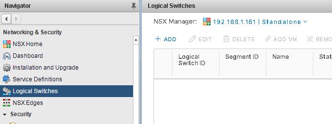
Navigate to Home > Networking & Security > Logical Switches.
Click Add for New Logical Switch
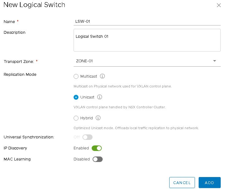
- Type a name and optional description for the logical switch.
- Select the transport zone in which you want to create a logical switch.
Note:- By default, the logical switch inherits the control plane replication mode from the transport zone.
- Select the Replication mode, here we choose Unicast. There are three available modes are unicast, hybrid, and multicast, you can choose as per requirement.
Note:- When the logical switch you are creating has significantly different characteristics in terms of the amount of BUM traffic it must carry, then you might want to override the inherited transport zone’s control plane replication mode for an individual logical switch. In this case, you might create a transport zone that uses unicast mode, and use hybrid or multicast mode for the individual logical switch.
- Enable IP Discovery to enable ARP suppression if required
- Enable MAC Learning if required
- Click on ADD
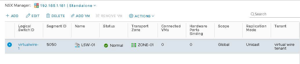
Now the Logical Siwecth has been created, you can click on Add VM from there to attach virtual machines to this switch
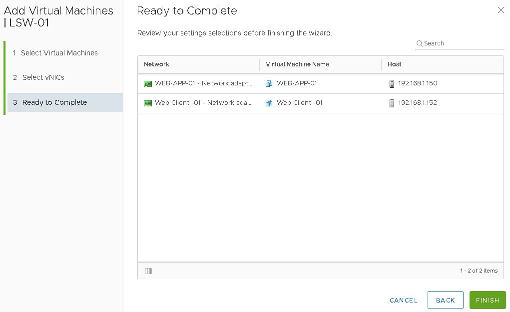
Select Virtual Machines from Available Objects
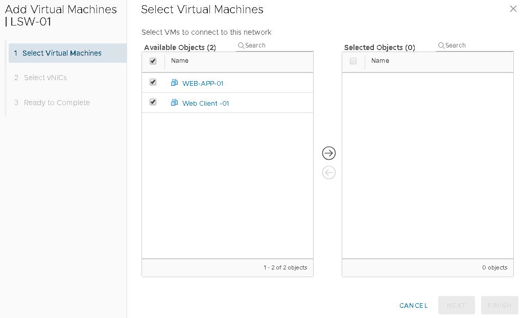
Move to the next Box – Selected Objects and Click Next

Assign the vNICS to the VMs and Click Next

Click on Finish
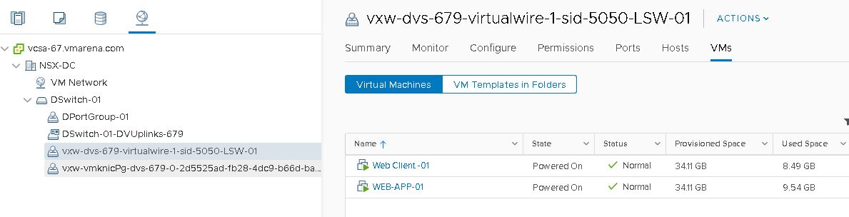
Logical switch that you created receives an ID from the segment ID pool, and a virtual wire is created. A virtual wire is a dvPortgroup that is created on each vSphere distributed switch. The virtual wire descriptor contains the name of the logical switch and the logical switch’s segment ID. Assigned segment IDs appear as shown below
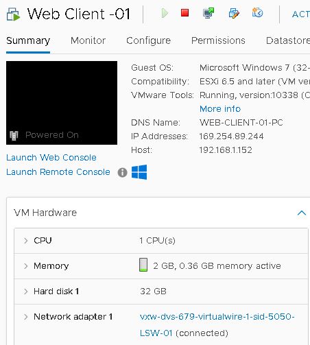
You can verify that VM connected Logical switch by navigating to Home > Hosts and Clusters > VM > Summary
Conclusion
In this article, we have shared the steps we followed to create Logical switch in our lab. We followed VMware documentation for each procedure to confirm that there is misconfiguration and follows the standard procedure .